Cathodic Insulation Kits
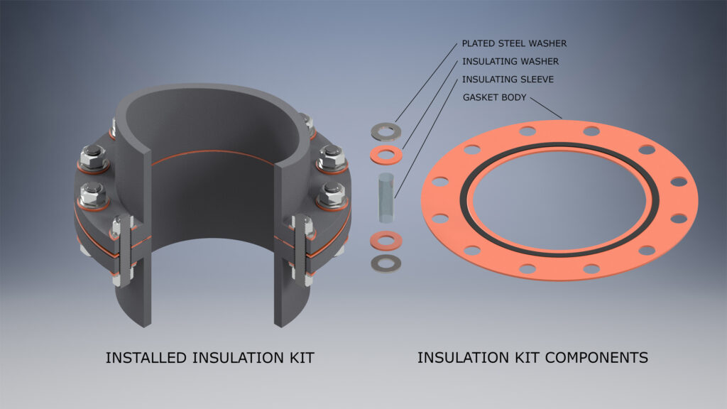
Cathodic Insulation Kits with Seal
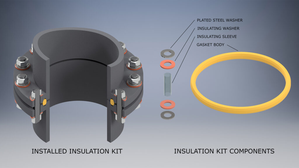
“Cathodic Insulation Kits with Seal” gaskets are made with a special O-Ring sealing element inlayed in the face of the gasket. This O-Ring creates a very flexible seal that requires less bolt or stud torque to maintain constant contact with the flanges sealing surface surface.
Cathodic Insulation Kits with Seal gaskets are available in both F and E styles.
The O-Ring seal and gasket are available in a wide variety of materials.
Type D
Type D gaskets are machined from a specified insulating material and are designed to fit ring joint type groove flanges.
BX gaskets are also available.
Available Materials: Hi-Temp G-3, G-7, G-10, G11, Phenolic
A 1/4” thick closed cell neoprene sponge flange protector is recommended to prevent the flanges from shorting out.
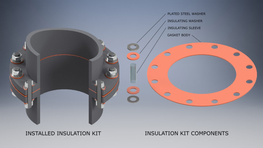
Type E
Type E gaskets offer complete protection for both flange faces. The gasket centers easily having the same outside diameter as the flange. This prevents foreign matter from accumulating between flange faces and shorting out the flanges.
Type EDC
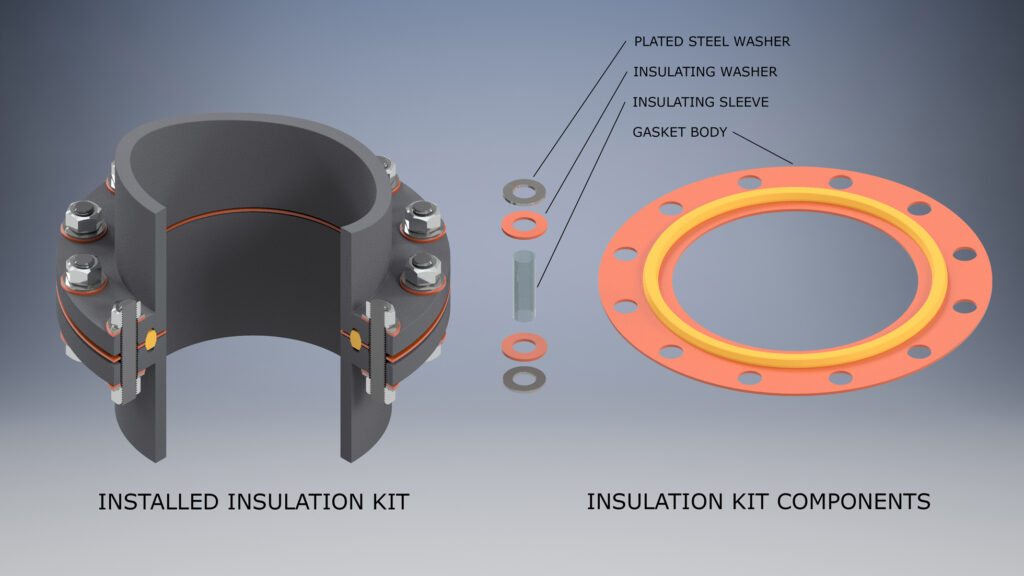
Type E-RTJ combination gaskets are are made with an insulating ring joint gasket and insulating inner and outer rings. This special design gasket offers complete protection for both flange faces. The RTJ gasket provides the seal, while the 1/32″ thick inner and outer barrier rings cover the I.D. to the O.D. This prevents foreign matter from accumulating between flange faces and shorting out the flanges. It is available in most sizes and materials.
Type F
Type F gaskets are fabricated to fit the raised face portion of the flange face and are designed to center on the inside of the bolt circle.
We recommend that a flange protector made from 1/4” thick closed cell neoprene sponge be used to prevent foreign matter from collecting between the flange faces.
Selections

Cathodic Insulation Kits With Seal

Full Face

Raised Face

RTJ
NPS
Nominal Pipe Size
4″
PSI
ANSI Pressure
150#
Gasket Type & Material
E, F, or D
NSEP
Washer
Single or Double
DW
Sleeve
Mylar
| Sealing | |
|---|---|
| NS | Nitrile |
| TS | Teflon |
| VS | Viton |
| GS | Graphite |
| QS | Non-Asb |
| Gasket | |
|---|---|
| G10 | G-10 Epoxy/Glass |
| G11 | G-11 Epoxy/Glass |
| HTG-3 | High Temp |
| N | Nitrile Coated Phenolic |
| P | Phenolic |
| Q | Non-Asbestos |
| R | Red Rubber |
| Washers | |
|---|---|
| SW | Single Washer |
| DW | Double Washer |
| Phenolic and Plated Steel Washers are standard
Other materials available on request are…
| |
| Sleeves | |
|---|---|
| G10 | |
| G11 | |
| Integral (Minlon) | |
| Mylar | |
| Nomex | |
| Phenolic (Micarta) | |
| Polyethylene (Poly) | |
| Teflon | |
Material Specifications
Flange insulation products are used worldwide for all types of piping and pipeline systems to isolate and prevent the flow of electric currents through a fluid or gas pipe system. A primary benefit is the control of damage caused by “electrolysis” and the danger of static electrical build up and subsequent discharge.
Kit Contents
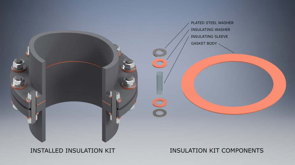
Each insulation kit contains an isulating gasket, insulating washers, steel washers and sleeves for each bolt or stud. Flange insulation gaskets are made in all sizes, pressure ratings and virtually all suitable materials. The size and shape of each varies depending on the flange type, size and pressure. Gaskets may be purchased in kits or separately. Related sleeves and washers are provided in the kits and available in all sizes and materials.
Flange insulation kits for large diameter flanges, flanges with special bolt hole configurations, or for uses in unique or unusual environments are available by special order.
Detailed Material Specifications Charts
Flange Specifications
Kit Contents
Each insulation kit contains an insulating gasket, insulating washers, steel washers and sleeves for each bolt or stud. Flange insulation gaskets are made in all sizes, pressure ratings and virtually all suitable materials.
The size and shape of each varies depending on the flange type, size and pressure.
Gasket Specification Sheet
In order to manufacture your order correctly please click the button below to fill out the form. If flanges are not identical, you must specify both flange thickness for sleeve to fit properly.
Note: Insulating Sleeve is designed to fit threaded studs. When using bolts with shanks, the sleeve may not slip over the shank and it may be nessesary to grind the shank to the diameter of the thread.
Kit Weight
| Full Face Gasket and Double Washer Set | |||||
|---|---|---|---|---|---|
| NPS | 150# | 300# | 600# | 900# | 1500# |
| 3/4” | 0.5 | 1 | 1 | 1.25 | 1.25 |
| 1” | 0.5 | 1 | 1 | 1.5 | 1.5 |
| 1 1/2” | 0.5 | 1 | 1 | 1.5 | 1.5 |
| 2” | 1 | 1.5 | 1.5 | 1.5 | 1.5 |
| 2 1/2” | 1 | 1.25 | 1.25 | 1.5 | 1.5 |
| 3” | 1 | 1.5 | 1.5 | 2 | 2.25 |
| 3 1/2” | 1.5 | 1.5 | 1.75 | 2.5 | 3 |
| 4” | 1.5 | 1.5 | 1.75 | 2.5 | 3 |
| 5” | 1.5 | 1.5 | 2.25 | 3 | 5.25 |
| 6” | 1.5 | 2.5 | 3.5 | 3.75 | 7 |
| 8” | 2.5 | 2.5 | 3 | 7 | 10.5 |
| 10” | 3.5 | 4 | 5.5 | 9 | 9.5 |
| 12” | 4 | 5.5 | 8 | 9 | 15.75 |
| 14” | 6 | 6.25 | 6.75 | 13.5 | 27 |
| 16” | 7.5 | 10 | 10.5 | 16.75 | 28 |
| 18” | 9.5 | 12 | 13.5 | 16.8 | 30 |
| 20” | 12 | 13.5 | 20 | 21 | 27 |
| 24” | 14.5 | 16.5 | 21 | 33 | 34.5 |
| 26” | 15.5 | – | – | – | – |
| 30” | 16.5 | – | – | – | – |
Bolt Torque
Torque Required to Produce Bolt Stress
The torque required to produce a certain stress in bolting is dependent upon a number of conditions, including:
- Diameter of bolt
- Type and number of threads on bolt
- Material of bolt
- Condition of nut bearing surfaces
- Lubrication of bold threads and nut bearing surfaces
The tables below reflect the results of many tests to determine the relation between torque and bolt stress. Values are based on steel bolts which have been well lubricated with a heavy graphite and oil mixture.
It has been found that a non-lubricated bolt has an efficiency of about 50 percent of a well lubricated bolt. Also, different lubricants produce results which vary from 50 to 100 percent of the tabulated stress fingers.
Click below to download more information
Installation
- Make sure that the insulation kit you received is undamaged and contains the materials and parts you requested.
- Check that the flange faces and fully threaded bolts are clean and lubricated.
- Install gaskets by carefully aligning over bore so gasket and bolts center.
- Alignment pins 3/32″ larger than bolts should be used in two opposing bolt holes to assure proper alignment of flanges.
- Place sleeves in open bolt holes. Do not force sleeve or damage may result.
- Place fully threaded bolt in insulating sleeve with insulating washer next to flange followed by the steel backup washer and nut.
- Tighten opposite bolts to 30% of the required torque.
- Remove alignment pins and repeat process.
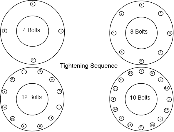
- Using a bolting diagram, tighten all bolts to 50% of their final torque value. Repeat torquing process until you have reached 100% of the required torque.
- Flange electrical shortout may occur if foreign matter is allowed to accumulate between the flange surfaces.
